With emergence of accelerometer, gyroscope and magnetometer on iPhone devices, new opportunities have opened up before iOS application developers. However, although their APIs have been announced for several years now, not much on them can be found on the Web today. On the one hand, this topic is really not so vast to dedicate a book or series of posts to it. But on the other hand, there are certain specifics and pitfalls you have to be aware of. This post is intended for developers who are willing to befriend accelerometer and gyroscope in the iPhone.
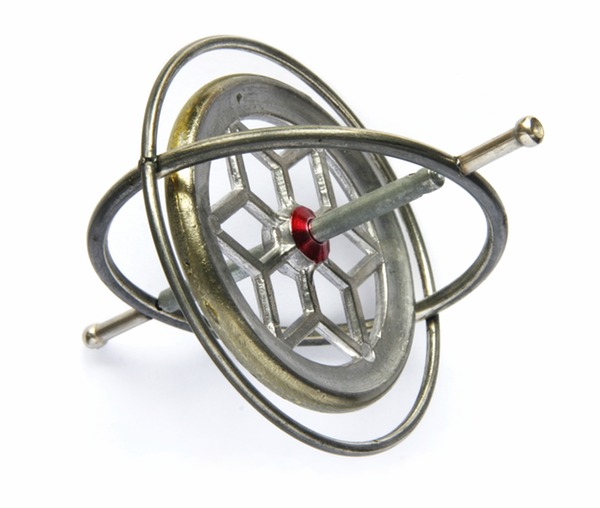
Some history first
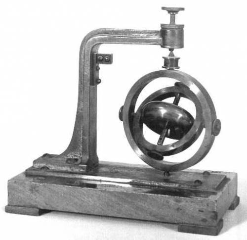
By making the phone capable to track its location and movement in space, Apple’s engineers have added a new dimension to gaming and augmented reality development, erasing one of many boundaries between the outside world and the software reality.
The first iPhone model had only an accelerometer and was able to determine its acceleration along all Cartesian axes. Apple has provided developers with access to the API of STMicroelectronics LIS302DL, an accelerometer included into the first iPhone model. Accelerometer methods were in the UIAccelerometer class.
However, accelerometer reports three degrees of freedom only (along the three Cartesian axes), but Apple’s objective was to ensure control for all nine degrees. Why are there nine of them? The answer is pretty simple: 6 degrees of freedom are from the classical mechanics (3 translations along the axes and 3 rotations around the axes), with three components of the Earth’s magnetic field around the device. So the device had yet to be told how to determine its rotations, orientation in space and direction of the external magnetic field.
The magnetometer was first introduced in iPhone 3GS, with a standard Compass application made to demonstrate its features. Finally, a gyroscope for measuring rotational speeds was introduced in iPhone 4. Also in this model, accelerometer and magnetometer have been replaced by newer and more advanced components. Starting with iPhone 4, we can say that it can keep track of all nine degrees of freedom. The same set of sensors is used today, in iPhone 5.
How to Use Core Motion
So that you are not bored, let’s now go right to the practice, making certain theoretical and historical digressions on the way.
All the device’s motion sensor features are implemented in the Core Motion framework. So, to be able to use sensor readings, first we have to add the framework to our project.
For illustration purposes, let’s create our project in XCode, showing readings from motion sensors in the main window. Please note, that you can test the functionality of Core Motion on an actual device only. This should in no way surprise you, as the simulator has no sensors.
So, edit your main view controller as shown in the picture below.
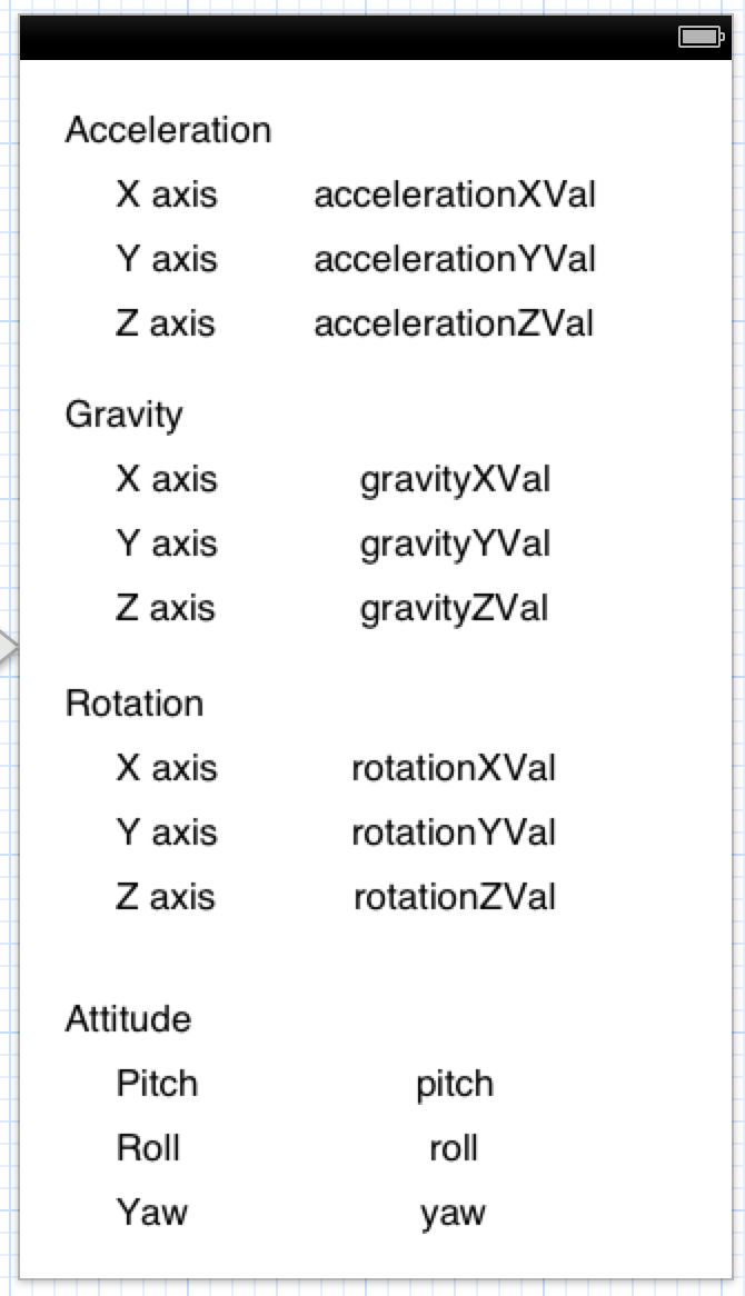
The first section, Acceleration, will display device acceleration along the three axes. The Gravity section shows projection of the force of gravity applied to the device. The Rotation section displays data on speed of device rotation around the three axes. Finally, the Attitude section shows device’s spacial orientation by three angles: Roll , Pitch and Yaw, like in aircraft rotations. Such angles correspond to the Euler angles used to describe the position of a solid in space.
XYZ coordinates are linked to the device and arranged as follows:
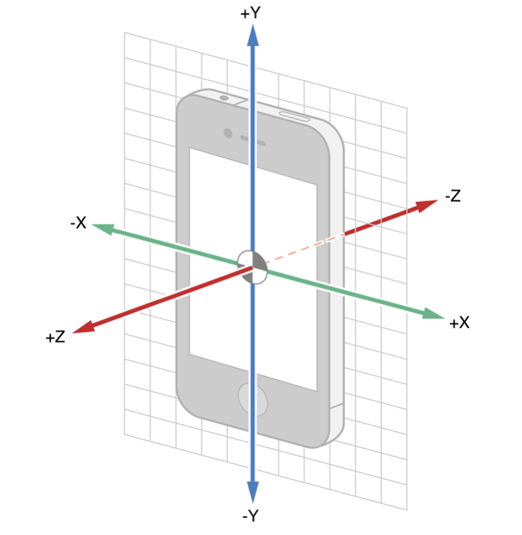
The accelerometer outputs three double type variables, representing three projections of the acceleration vector on the axes.
The speed data from the gyroscope also arrive as axial rotation components. The sign of each rotational component is determined by the rule of thumb.
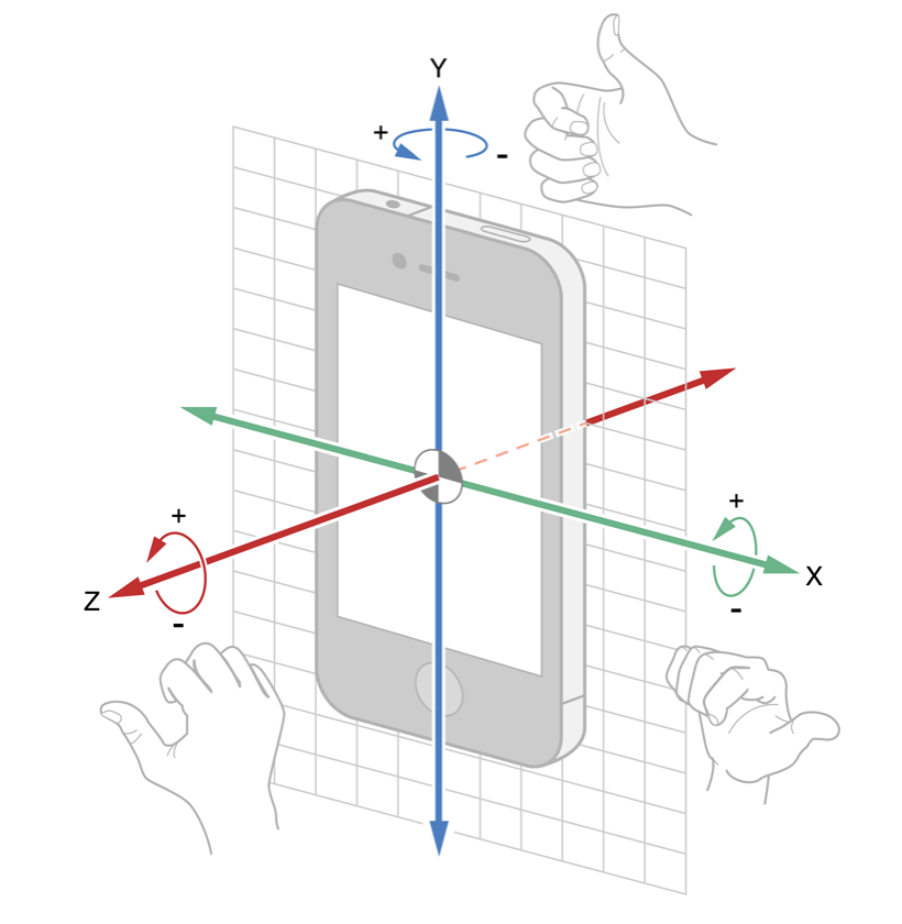
The accelerometer data is measured relatively to the acceleration of gravity (g). The gyroscope data is measured in radians per second.
To bind all the UILabel objects (they are all located to the right) to the controller, create IBOutlet properties for them. Then, create two more properties: CMMotionManager and CADisplayLink.
CMMotionManager is the basic class of the Core Motion framework, providing access to the API of all sensors. CADisplayLink is the class we use as a timer running at the screen refresh rate.
Having created CMMotionManager, set the refresh rate, depending on your sensor utilization context. The higher is the refresh rate, the more CPU resources Core Motion will consume. The lower is the refresh rate, the slower the data will be updated. Higher frequencies may be needed to ensure prompt device response to movement. Generally, to select frequency, we recommend that you use the table from the official documentation.
In our test project, we have chosen refresh rate of 30Hz equivalent to 30 updates per second.
Now, add a separate method to the controller to output updated values to the screen:
[gist id=6051927]
As we have already mentioned, we are going to use the CADisplayLink class as a timer. It will call the updateMotionData method at the device refresh rate. The method receives data by accessing the deviceMotion property and its fields. Such type of data retrieval from the sensors, when you request new data from CMMotionManager, is called the pull method.
As an alternative, you can also use the push method. The core distinction of push against pull is that with pull you can lose some of the data, since you are deciding when to read them. The data can update for a few times between your pulls. With the push method, you are not going to miss any reading, as CMMotionManager delivers the data to you at the refresh rate. For this purpose, it receives a code block to be invoked every time the new data arrives.
As far as the method selection is concerned, framework developers advise that, in most cases, pull is all you need. Push might be required if it is critical not to miss any data. However, this is rarely needed in case of common user applications and games. It’s more of a prerogative of research applications. In addition to higher processing costs in case of push, you will also be unable to slow down the data retrieval, if your application performance degrade. By the way, each data reading has a timestamp: so you can always be aware how much readings you have missed in case of pull.
So for our testing purposes we have chosen pull. As you can see from the updateMotionData method, we retrieve the data both from the gyroscope (rotation and attitude) and accelerometer (acceleration and gravity). The complete controller code is as follows:
[gist id=6051762]
Launch the app on your device, roll it around the axes, view the changes of sensor readings. The easiest part of the work is done. Now, let’s start experimenting.
One Soldier Doesn’t Make a Battle
If you have already referred to the CMMotionManager documentation, you have probably noticed that it provides methods to retrieve the data directly from the gyroscope, accelerometer and magnetometer. So why have we used the tricky deviceMotion instead, and what is it all about? First of all, let’s go into a bit of experimenting, backing it with a bit of history.
When creating a CMMotionManager object, in the same place where you have set the refresh rate, set the same refresh rate for the accelerometer and gyroscope.
_motionManager.accelerometerUpdateInterval = kCMDeviceMotionUpdateFrequency; _motionManager.gyroUpdateInterval = kCMDeviceMotionUpdateFrequency;Then, in the viewDidLoad method, replace line
[Self.motionManager startDeviceMotionUpdates];with
[Self.motionManager startAccelerometerUpdates]; [Self.motionManager startGyroUpdates];Finally, in the updateMotionData method replace acceleration retrieval (block //1) and rotation retrieval (block //3) from deviceMotion, with the applicable devices.
//1 CMAcceleration acceleration = self.motionManager.accelerometerData.acceleration; //3 CMRotationRate rotation = self.motionManager.gyroData.rotationRate;Now, run the test. Put your phone on a flat surface. Let’s analyze what we can see now. When a phone is lying flat on the table, according to the accelerometer readings it has got a vertical acceleration approximately equal to 1, that is, to the acceleration of gravity. This is not the only miracle we have observed here. Look at the pure gyroscope’s readings: the unmoving phone also has a rotational speed.

How can this be possible?
Now, let’s go into the historical digression we have promised to you. The very first tests of the accelerometer on the first iPhone model has shown that, all its fun is spoiled by a relatively high level of noise caused by the sensor itself. To be more exact, it was affected by gravity.
By definition, in addition to its own acceleration the accelerometer is also pulled by gravitation. Using digital signal processing (both high-pass and low-pass filters), the iOS SDK developers succeeded to isolate the vector of gravity from the overall data flow. And this was really good news, as detecting the vector of gravity is part of the job to determine spacial rotation of the device. We say "part of the job", because you cannot determine rotation if it occurs around the gravity vector, as its direction is not changing in such a case.
Application developers, in their turn, had to receive "pure" device acceleration, without the affect of the gravity vector. And here is where the bad news emerge, because separation of the total flow of data by acceleration and gravity is performed using two filters: high-pass filter, for gravity, and low-pass filter, for acceleration. However, the more filtering we apply, the more valuable data we lose, and hence the sensor becomes less responsive. This resulted in degraded accuracy, and the gravity vector could have been used to determine position but tentatively.
The emergence of the gyroscope has not alleviated the situation. For the capability to read rotational movements of the device and its full orientation in Euler angles, we had to pay with a new issue, i.e., shifft of sensor readings. You may have noticed that, when the phone has been fully stationary, the gyroscope readings were stable, however non-zero. It means that there has been some constant error. Even worse, when integrating the speed to determine angular position, the non-zero error resulted in a linearly growing error! Just in half a minute of using a gyroscope, the telephone was 45 degrees from its actual position.
So, it quickly became evident that sensors and algorithms of data retrieval are not as perfect as desired. Used separately, the sensors are clearly not so good. But the truth is somewhere in between, as usual. A solution to the problem was to make accelerometer and gyroscope work together.
We have found, that accelerometer and gyroscope combined can overcome all the above issues. iOS SDK developers have implemented ad-hoc algorithms to mutually improve the sensor operation. Those have become part of iOS 4, the first iOS version introducing Core Motion in its full splendor, including methods to accurately determine acceleration, rotation, and spacial orientation. Joint readings of the sensors are now free from noise and errors and are combined in the deviceMotion property. Now, you do not need to apply filtering to isolate the acceleration vector from gravity, as deviceMotion contains them separately (as user acceleration and gravity). Since the gyroscope no longer has a constant error, it has now become possible to accurately determine the phone’s spacial orientation.
Having completed this simple experiment, you now know why you should always prioritize deviceMotion against plain gyroscope or accelerometer readings. Let alone deviceMotion do some extra job if what you need is acceleration only or rotation only, you can rely on accuracy of such data.
Gimbal lock
Now we have but a final section of our test, Attitude. At the first glance, nothing is complex here. All the angles duly change their value at device rotation. However, if we look closer, we can see that yaw can sometimes flip by somewhat 180 degrees at other angles’ change. So it means that changes in roll and pitch can affect yaw. So probably you are eager to know, what happens?
This post provides details of the issue called gimbal lock, along with its effect on Euler angles. The author also has mentioned the 180 degrees flip which you surely would like to avoid if animation of any on-screen objects depends on yaw.
The post also mentions that a common way to avoid gimbal lock is to avoid Euler angles in favor of other ways of describing spacial orientation. Particularly, you can use quaternions.
To make yourself familiar with quaternions, take any reasonable textbook on linear algebra, or just read about them on Wikipedia. But how can we get quaternions for each particular orientation? That’s what the Core Motion developers have already taken care of, as the quaternion property is part of deviceMotion. The property has the CMQuaternion type and is a structure consisting of four double type values. Now, to derive the Euler angles from quite counter-intuitive quaternions, use the well-known transformation formulas.
An alternative is to use the rotationMatrix property which is also free of gimbal lock. However, deriving angles from matrices is sort of a more complex task compared to quaternions. It has been assumed that, matrices can be used by developers to integrate with OpenGL ES.
Reference Frame Configuration
Finally, let’s discuss the reference frame setup. The reference frame is a basic orientation of the device’s coordinate system taken as a reference. All the subsequent values of Euler angles are measured from it. It is sort of a "zero reference point" for the orientation. So, by setting a new reference frame you can specify a new initial position of the coordinate axes. This might be helpful for augmented reality applications, where it is often necessary to constantly monitor the north direction. Just select a relevant reference frame, and your device orientation will be, at the same time, its decline from the magnetic north (or the North Pole, if you like).
Let’s now ask ourselves, what is the reference position for the device orientation angles, or what is the default "zero" point? The initial orientation of a device is where it has been when having initially received data from the sensors. Such position is then modified so that its Z-axis is oriented vertically upwards opposite to the gravity vector. The X and Y-axes, therefore, would be the projections of those axes on a plane perpendicular to the Z-axis. Such orientation is the default reference frame.
Is it possible to set a reference frame in iOS? In iOS 4, yes, partially. In iOS 5, definitely, yes. Let’s consider iOS 4 first. Objects of the CMAttitude class representing spacial orientation of the device, contain the multiplyByInverseOfAttitude: method. As an argument, this method accepts an object belonging to the CMAttitude class. By passing a certain device orientation to this method, you can calculate the angular difference between the orientation that has called the method and the orientation passed to the method. This way, you can get a deviation from the position which is not a true reference frame. The downside of this approach is that you have to receive and store the desired position and consume computing resources to execute the specified method.
In iOS 5, developers can now set the reference frame when starting to receive the sensor readings. The reference frame is passed to one of the methods:
- (void)startDeviceMotionUpdatesUsingReferenceFrame:.
- (void)startDeviceMotionUpdatesUsingReferenceFrame:toQueue:withHandler:.
However, you cannot specify an arbitrary reference frame. You can just choose from 4 presets.
- CMAttitudeReferenceFrameXArbitraryZVertical is a default option mentioned above. The Z-axis is directed vertically upwards opposite to gravity, and the X-axis is along a projection of the real X-axis to the plane perpendicular to the Z-axis.
- CMAttitudeReferenceFrameXArbitraryCorrectedZVertical is a modification of the previous option. The only difference is that it involves the magnetometer. It helps to modify the orientation algorithm to exclude the growing error in the yaw angle. Its downside is additional CPU cost. Also, if you are close enough to a heterogeneous magnetic medium, this reference frame is likely to become erroneous.
- CMAttitudeReferenceFrameXMagneticNorthZVertical is, probably, the most helpful option. The X-axis of this reference frame is always pointing towards the magnetic north. It means that this option is again using the magnetometer. Please note that the magnetometer needs to be periodically calibrated. To call the standard calibration screen, just set the showsDeviceMovementDisplay property to YES.
- CMAttitudeReferenceFrameXTrueNorthZVertical is identical to the previous option, but instead of magnetic north the X-axis points to the true north. It consumes the greatest amount of CPU resources, because beyond using the magnetometer it makes additional calculations to make a transformation to the true north.
So this is the set of reference frames you have. Prior to using a particular reference frame, check for its availability in the system by calling class
+ (void)availableAttitudeReferenceFramesConclusion
Congratulations, you have read this post to the end!)

Motion sensors in iOS is really a wonderful tool. As all the augmented reality applications, they are enchanting us by bringing the information about our environment to our phones’ virtual realm. Also, let me give their due to Apple’s engineers, the process of adding sensors to an application is extremely simple, and their further use is in no way restrictive, opening an unlimited space for your creativity.
Although it would be too garish to say that we have opened up a new dimension in application development to you, at least we hope that you have learned some really fascinating facts about the Core Motion framework from this post. We would be happy to further inspire you to creating new applications offering exuberant augmented reality experience to your users!
In the next post, we will tell you about our new component, DVParallaxView and provide a visual example of how to implement parallax based on Core Motion.